Transformers for DAC output stages
TYPE
(DAC Type)
(Ohms)
dia
(mm)
height
(mm)
Very high bandwidth type
secondary
High ratio

Transformers for DAC output stages |
||||||
| Link to shop | Link to spec TYPE |
Application (DAC Type) |
Ratio | I/V resistor (Ohms) |
Can dia (mm) |
Can height (mm) |
| 1465 | Current out. Very high bandwidth type |
1+1:5+5 | 8.2 K Ohms secondary |
45 | 52.5 | |
| Buy | 1495 | Current
out High ratio |
1:9+9 | 100 Ohms max | 34 | 39 |
| Buy | 3603 | Voltage out type |
1:1 | none | 34 | 24 |
| Buy | 9335 | Attenuator | none | 45 | 52.5 | |
The sound quality of almost any commercial CD player or digital music systems can be improved by the use of a transformer to perform the current to voltage (I/V) conversion. There are 3 reasons for this:
1.The usually rather poor operational amp chips which are fed by the I/V resistor are eliminated.
2.The digital and analogue grounds can be isolated which can remove some complex distortion mechanisms.
3.The unique frequency characteristics of the transformer can provide improved filtering of the quantization noise.
The schematic below shows how to connect type 1465 to a CD player. two transformers are required for stereo.
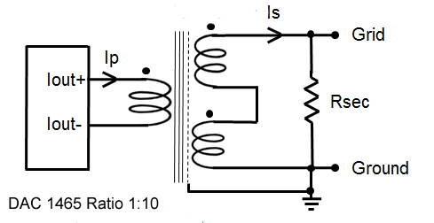
The Iout + and - should be disconnected from the existing circuit and conected to the primary. The secondary windings should be wired in series and connected between the amplifier grid and ground. The internal electrostatic screen should be connected to analog ground. It is important not to conect the amplifier ground to the digital ground of the CD player. The I/V resistor (Rsec) should be connected across the secondary of the transformer as shown. Analog voltage out DAC's cannot be used with 1465 or 1495.
AD1860N AD1862 AD1865DSD1792PCM1702 PCM1704 PCM1738 PCM1792 PCM1794 PCM1795 PCM1796 PCM1798 PCM2702 PCM56 PCM63 TDA1540 TDA1541A TDA1543 TDA1545A TDA1547
AD1852 AD1853 AK4396 AK4399 AK4440 AK4490 AK4455.95 CS43122 CS4390 CS4398 ES9018 ES9038 EVM1072 SAA7350 WM8740 WM8741
HOW TO CALCULATE THE I/V RESISTOR:
We recommend using a resistor across the secondary of the transformer. This example assumes the input impedance of the amplifier is high.
First calcualte the primary rms current.. If the output current pf the DAC is 4 mA p-p, This is 4 x 0.354 = 1.4mA rms.
Next calcualte the secondary current. Divide the input current by the ratio. So if the ratio is 1:10 the output current is 1.4 / 10 = 0.14 mA rms. = 0.00014 Amps.
Now choose the resistor. Use Ohms law: R = V / I. So if you want 1v rms, R = 1 / 0.00014 = 7142 K Ohms.
We have to allow for some insertion loss in the transformer, about 20%.. Nearest value 8.2 KOhms.
NOTES: This will work well provided the secondary feeds a high impedance such as a valve grid. It should be apparent that it is possible to adjust the I/V resistor and transformer ratio to get a different output voltage but it should be born in mind that most DACs work best with a low I/V resistor. The value of the I/V resistor as seen by the DAC (the reflected secondary load) can be calculated by dividing by the ratio squared.
PARALLED DACS: Multiple DAC modules can be wired with the iout terminals in parallel to increase the current into the transformer. This will enable increased output power from the transformer to drive the load.
Increasing the current into the transformer does not cause the core to saturate. This is because ac current flowing into the primary is always accompanied by an equivalent current out of the secondary so it does not cause magnetisation of the core. Magnetisation (flux density) is proportional to the applied voltage and inversly proportional to frequency.
PRODUCT OFFERING: We offer a range of transformers suitable for most Digital to Analogue Converters (DAC's). Multi-section winding techniques are used to maximize bandwidth and transient response. All our DAC transformers are constructed on Mumetal (76% Nickel) cores for minimal distortion and contained in heavy gauge Mumetal screening cans. Some models have multiple internal electrostatic shields are provided to minimize noise pick-up.
Type 1465 is designed for most popular applications. It has has a twin bifilar primary windings which may be used in parallel driven from one DAC or may be used with twin DAC's carrying out of phase signals. These are subtracted by the transformer which provides the ultimate in cancellation of quantisation noise .
Type 1495 is provided for customers who want a high ratio transformer which can be used when feeding a high impedance input (like a valve grid). It can be configured as a 1:9 or 1:18 ratio and is also a lower cost option.