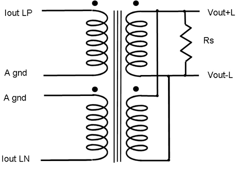
APPLICATION Our most popular transformer for use with most current out Digital-to-Analogue Converters. Works well with any current out DAC. Provides current to voltage conversion with gain to achieve at least a line level signal (0 dBu 0.775V) depending on the I/V resistor used. Presents a low impedance to the DAC output for best frequency response and quantisation noise reduction. . Provides significant sound quality improvement when compared to other interface methods. Ensures full isolation of digital noise in ground and supply rails. We recommend that the I/V resistor is placed across the secondary of the transformer (See below). The transformer has sufficient inductance for good quality operation with higher values to increase the output level.. Lower values may improve the sound but will reduce the output level. Can be configured to drive 9335 attenuator without loss of bandwidth. Can be used driven from multiple parallel DAC's to increase output level. Twin primary windings are provided for use with twin DAC's fed with complimentary data. This approach has been used in order to cancel out quantisation noise. The I/V resistor across the secondary of the transformer instead of the primary has yeilded the best result according to some customers. The value of the resistor should be increased by the ratio squared. The table below suggests values for rexperiment. |
|||||
FEATURES Exceptionally
large and high performance transformer. Twin primary windings are provided for use with two DAC modules fed with complimentary digital signals which provides improved cancellation of quantisation noise. For normal use connect the two primary windings in parallal. Twin secondary
windings with geometric balance for driving differential (push-pull) amplifier. These may be used
in parallel to improve the bandwidth and reduce the output impedance. Mumetal core for
minimal harmonic distortion. Mumetal can for magnetic shielding. |
|||||
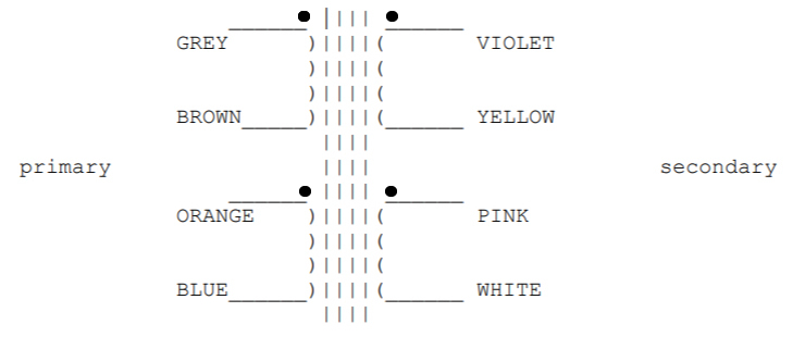
HOW TO CONNECT THE WINDINGSReferring to the diagram below: To connect the primary windings in parallel (usual configuration) connect Grey to Orange and Brown to Blue. To connect the secondary windings in parallel connect Violet to Pink and Yellow to White. To connect in series connect Yellow to Pink. If you are driving a balanced input it is normally better NOT to ground the mid point (Yellow-Pink). For feeding an unbalanced load one side can be connected to analogue ground. For feeding 2 grids Yellow-Pink can be grounded to reference the grid bias. If possible the grounds of the digital part of the circuit should not be joined. The secondary may be loaded balanced or unbalanced (one side grounded). |
|||||
HOW TO CALCULATE THE I/V RESISTOR (example)Current out = +/- 2 mA = 4 mA p-p = 4 / 2.82 mA= 1.43 mA |
|||||
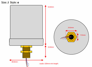
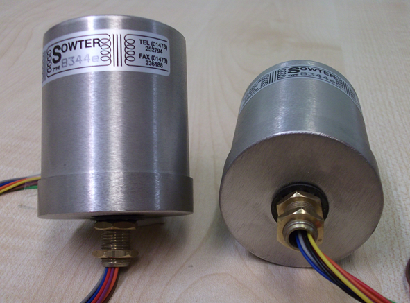
CAN DIMENSIONS |
45 mm Dia. x 52.5 high |
||||
PRIMARY INDUCTANCE (each coil) |
3.0 H Typical |
||||
PRIMARY DC RESISTANCE (each coil) |
6.7 Ohms Typical |
||||
SECONDARY DC RESISTANCE (2 coils in series) |
1.29K Ohms Typical |
||||
RATIO |
1+1:5+5 |
||||
FREQUENCY RESPONSE (Typical) |
Parallel secondary windings |
+/- 1.5 dB 5 Hz to 100 kHz |
|||
Series secondary windings |
+/- 1.5 dB 5 Hz to 50 kHz |
||||