1 WHAT IS THE "IMPEDANCE" OF A TRANSFORMER?
The impedance (more correctly, "nominal impedance") is really no more than a label which can be attached to a transformer or a winding. The nominal impedance just gives an idea of the impedance of the circuit in which it could be used. If you measure the impedance of the primary winding you will see the "reflected" impedance of the load you connect to the secondary winding.
If the secondary is left unconnected you will measure an impedance which is a function of the primary inductance and of course the result will depend on the frequency of measurement. We normally design transformers so that the measured impedance is about 3 x the nominal impedance at the lowest frequency, typically 20Hz.
"Reflected" means multiplied by the turns ratio squared. For example if you connect a 10,000 ohm resistor to the secondary of a 1:10 step up transformer and measure the input impedance you will measure approximately 10,000 X (0.1 squared) ohms i.e.100 ohms. (This is only approximate because you will need to allow for the primary inductance and the dc resistance of the windings).
2) WHAT IS THE INDUCTANCE OF A TRANSFORMER?
In very simple terms it is a measure of the number of turns on the coil, the dimensions and the permeability of the core. We normally talk about the inductance of a winding, usually the primary. The greater the inductance, the greater the ac resistance or the impedance of the winding. The impedance of an inductor increases proportionally to frequency. The inductance is also a function of the degree of magentisation (the appled voltage) because the core materilal behaves differently depending on the flux density.3) DO IMPEDANCES HAVE TO BE MATCHED?
In many circuits the answer is NO. Generally the lower the better for a source and the higher the better for a load. For example a 50 ohm source would drive a 10K load perfectly even via a long cable. Problems arise only if the mismatch loads the source. For example a 10K source driving a 600 ohm load would have considerable insertion loss because most of the signal voltage would be lost across the internal (10K) resistance of the source. A 600 ohm source driving a 10K load is fine.4) WHEN DO I NEED A TRANSFORMER TO MATCH IMPEDANCES?
When you want a step up or step down of voltage or when the source has an impedance which is high compared with the load. You cannot match a high impedance source to a low impedance load without a step down in voltage.5) WHAT DOES dBu MEAN?
dBu is a voltage based decibel unit referred to 0.7746 Volts. 0 dBu = 0.7746 Volts, +10 dBu = 2.45 Volts, +20 dBu =7.746 V, +30 dBu = 24.49 Volts, +40 dBu = 77.46 Volts etc. dBu is numerically equal to dBm which is referenced to 1 mW into 600 ohms (= 0.7746 volts).6) HOW CAN I MEASURE THE IMPEDANCE OF A VALVE OUTPUT TRANSFORMER?
To measure the reflected load, Ra-a, you need to make a voltage ratio measurement. Apply a low ac voltage (6.3v from a heater transformer is ok) to the secondary and measure the voltage on the primary (anode to anode). You can use a scope or voltmeter. The voltage ratio is the primary voltage divided by the secondary voltage you used. The primary impedance will be the ratio squared x the secondary impedance. For example, if the secondary is 16 ohms and the ratio 20 the primary is 20 x 20 x 16 = 6400 ohms.7) HOW DO 100V LINE TRANSFORMERS WORK ?
Start by assuming the line is 100V when the amplifer is driving the full rated power. Some speakers have a transformer built in but if not it needs to be designed so that it delivers the rated power to the speaker when supplied with 100V. The transformer needs to be designed for a specified speaker impedance. If the amplifier is not designed to drive a 100V line it needs to have a transformer so that at full rated power it delivers 100V. The transformer needs to be designed so that the amplifer sees the reflected load which corresponsd to the power rating.
Useful formula V = SQRT(R x W). Example a 1200W amplifier feeding 8 Ohms: V = SQRT (8 X 1200) = 100V approx.
If you turn the volume up so the maximum power of the amplifier is exceeded either the overvoltage or the overcurrent sensor should trip. If you put too many speaker loads on the line so that the max amplifier power is exceeded the amplifier overcurrent sensor should trip.
If the line is not loaded enough and you wind the volume up too much the overvoltage sensor should trip.8) MY PUSH-PULL AMPLIFIER DISTORTS ON HIGH POWER. WHAT SHOULD I LOOK FOR?
You can eliminate the transformer as the cause of the distortion by applying a sine wave at say 500Hz. At this frequency and above the flux swing is minimal so the transformer cannot be saturating. You should also check the dc quiescent current on each side to check the unbalance current is not saturating the transformer. A few mA is ok.
Next you should eliminate parasitic oscillation. You can usually see this on a scope. Some circuits will burst into oscillation at the peaks of the signal and sound and measure very like distortion.
Finally scope the anodes to see if either side is bottoming (anode falling below the grid). This will also limit the power.
9) I AM EXPERIENCING HUM ON MY RECORD DECK. WHEN I TOUCH THE CARTRIDGE THIS ELIMINATES THE PROBLEM BUT IT RESUMES WHEN I LET GO.
I suggest the following steps.
1)Ensure the safety ground connecting metal parts of the turntable to the earth pin on the mains plug is connected properly.
2)If there is a grounding lead (usually a single black wire) from the turntable to the chassis of the amplifier make sure this is connected. If so try disconnecting it. If this stops the hum disconnect it. (Not very likely). Do not disconnect this if there is no safety ground as 1) above.
3)Unplug both audio (RCA phono) connectors and turn volume to normal level. If this stops the hum then our type 3575 isolator will probably solve the problem. If just connecting the ground of the phono connector brings the hum back then it is almost certain that a 3575 will work.
3575 has colour coded leads but no connectors. You will have to organise this yourself. You will need two transformers for stereo.
10) HOW CAN I MEASURE THE OUTPUT IMPEDANCE OF MY CD PLAYER ETC?
You will need a voltmeter and some resistors or a pot. Apply some signal... ideally a tone but you can you can use music. Measure the output voltage. Then connect a resistor to load the output. Adjust the resistance till the voltage drops to 50% of the unloaded value. The output impedance equals the load you applied.
11) SHOULD THERE BE A CENTER TAP on the secondary winding of a transformer to drive balanced or unbalanced audio line.?
For driving a balanced audio line a center tapped winding is not necessary. In fact a grounded center tap can cause ground loop problems and negate the advantages of the balanced line.
I know this does not quite feel right but what happens is that the signal automatically "floats" and assuming the load is balanced it will automatically balance itself about ground. The point is that "ground" is not really defined and may have noise on it so it is not a good idea to try to force the signal to be referenced to it.
If the load was perfectly balanced grounding the center tap would not make any difference because no current would flow via the center tap but any unbalance of the load would cause ground currents to flow.
Another advantage of not grounding a center tap is that If the load is unbalanced (i.e. one side is grounded) everything works and the source and load are still isolated from ground noise.
The only situation where you need a center tap is when you are driving a push-pull amplifier stage where the grids of the valves need to be tied to ground.
12) I HAVE CONNECTED MY PHONO CARTRIDGE TRANSFORMER BUT I GET HUM
It is usually because of a grounding problem. Click here for more information
13) WHAT TRANSFORMER DO I NEED TO GENERATE THE WARM SATURATION SOUND OF THE 70's. SOMETIMES CALLED COLOURTION?
If you just want to add a transformer to a piece of equipment I normally recommend our type 3575 for this. It can be driven from any impedance but needs to be loaded on the secondary with not less than 10K Ohms.
There is a lot of misinformation about transformer saturation behaviour. Saturation means applying a signal of a level and frequency which causes the flux density to exceed the linear range. The most common misunderstanding is that flux density depends not just on applied voltage but frequency as well. This means that mid and high frequencies only activate a very low flux density. This is the reason a transformer only tends to saturate with low frequencies. Th maximum level to avoid saturation is normally quoted at 20 or 50 Hz.
If you want to generate harmonic colouration this is best done with a non-linear amplifier device such as a triode. You need a good transformer to faithfully reproduce the pleasing sound generated by the electronics. This means minimal harmonic distortion, low phase shift and high bandwidth. (Like a 3575) A transformer will also eliminate undesired effects due to unbalanced signals or ground currents.
14) WHAT IS THE DIFFERENCE IN MEASURED AND SONIC PERFORMANCE OF OCC WIRE?
OCC means Ohno Continuous Casting. A process for making wire invented by professor Ohno of the Chiba Institute of Technology in Japan.
OCC wire has essentially zero crystal boundaries as well as a very low level of impurities relative to the commercial copper wire we normally use for our products.
You can read more at www.sowter.co.uk/occ.php
As explained we are not making any claims as to possible benefits from using this wire but we are making it available for customers to do their own experimentation. Obviously we are very interested to hear peoples opinions, theories and experimental results.
WHAT IS THE DIFFERENCE BETWEEN CHOKES FOR CHOKE INPUT FILTERS AND PI FILTERS?
There is no difference in the construction of CIF and PIF chokes. The difference is the rating because the choke in a CIF has to support ac voltage flux of several hundred volts whereas the PIF choke only has to support ripple voltage.If you want to use, for example CA15 as a CIF you can do so if you reduce the dc current to say 100 mA instead of 200 mA. You could determine the safe current by experiment. Simply increase the current till the choke makes a buzzing sound. (This is the core saturating) You can increase the safe current somewhat by using a small capacitor e.g.0.1 uF upstream of the choke. This will reduce the buzz and enable you to increase the current. It will also change the dc voltage you get.
16) I HAVE AN AUDIO TRANSFORMER BUT I DONT KNOW WHAT IT CAN BE USED FOR OR WHICH LEAD IS WHICH?
Measure the dc resistance between each lead combination. Group leads which are connected. Each group will be a winding. If the winding has more than 2 leads then it must be a tapped winding. Work out which leads are the ends of the winding and which are the taps. Now you have the dc resistance of each winding. Multiply the dc resistance by 10 to 15 and this will give you the approximate nominal impedance. For example if a winding measures 700 Ohms it is likely to be a nominal 10k impedance. Now you have the impedance ratio. You can probably determine if taps are a center tap (CT) or some other tap. Don't expect a CT to be at exactly half the resistance of the whole winding. If the tap is at 20% of the dc resistance it will be at 10% of the impedance.
You cant really check the maximum level by measuring dc resistance except that generally thre higher the impedance, the higher the level capability. You can measure the level capability with a scope but remember it will reduce with frequency.
17) CAN I DAMAGE A MUMETAL TRANSFORMER BY PASSING DC THROUGH A WINDING? CAN IT BE PERMANENTLY MAGNETISED?
Mumetal has a very high permeability so it magnetises very easily but it also has a very low reminance which means when the field is removed the "permanent" magnetism is effectively zero (very small compared with the saturation flux density). The core cannot be damaged or permanetly magnetised by applying a dc current.
We have a number of highly respected customers who have observed that the quality of sound associated with Mumetal transformers improves after a period of "burn in". Some customers even have particular pieces of music they use. We do not know of any scientific evidence for this but it is thought that this could be due to a reminance effect or perhaps "conditioning" of the listeners ears or brain.
18) WILL YOUR "CLONED" REPLACEMENT VINTAGE TRANSFORMER SOUND THE SAME AS THE ORIGINAL?
In order to make a replacement transformer for vintage products we determine the basic parameters e.g. voltage ratio, primary inductance, maximum level and dc resistance together with any dc requirement. We do this by reference to the schematic and the specification of the equipment and valves etc. Where possible we compare these parameters with an actual sample. We use the same core material as the original and the same lamination size if this is available. If not we try to use a larger size.
We do the design based on our long experience going back nearly 75 years and our own criteria for what results in the optimum design for the particular application. Our target is always to have a performance as good as or better than the original particularly with regard to bandwidth and distortion. Obviously we test samples and follow up with the first few customers. We regularly get very positive reports. If there are any issues we ensure the design is updated till the result is as expected.
We quite often get asked if the transformers sound like the original. The answer is definitely yes but bear in mind the characteristic sound is more determined by the circuit itself. If as we hope our transformer is better than the original then we expect it to sound even better than the original.
Please note that the physical size and mounting method may be different to the original.
19) I HAVE A CD PLAYER WITH A LOW IMPEDANCE BALANCED OUTPUT DRIVING A HIGH INPUT IMPEDANCE AMPLIFIER. SHOULD I USE 600/600 OR A 10K/10K TRANSFORMER?
This question comes up quite often and it is a dilemma!
You have a voltage source driving a high impedance load which is an ideal situation. In order to ensure a balanced load on the source and ground isolation you need a transformer. You already have a balanced source so this is ideal for driving a balanced cable. So far so good.
A 10K transformer has a high shunt inductance but a high series resistance. So which is better a high shunt inductance or a low series resistance? With a high input impedance of the pre amp series resistance does not matter and with a low source impedance shunt inductance does not matter. So perhaps it makes no difference!
We recommend a 10K/10K to preserve the beautiful high input impedance you have with your preamp and you can be sure of not getting any maximum level issues at low frequencies. The transformer should be connected as close as possible to the receiver.
20) TRANSFORMER WINDING DIAGRAMS. POLARITY, PHASE, PRIMARY/SECONDARY. WHAT DOES THE DOT MEAN?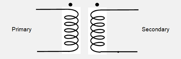
The dots mean the same polarity.
If there is no dot, the top of each winding on the diagram is the same polarity. i.e. Hot at the top of the primary is hot at the top of the secondary.
The top of the winding (or the dot) is the start if the winding, The start of the winding has less stray capacitance than the finish so it is best to make this the hot side of an unbalanced source. It should be the anode end of a power transformer.
On the diagram the winding on the left is the primary and the winding on the right is the secondary. The primary is normally connected to the source and the secondary is normally connected to the load.
If for example the transformer is described a having a 1:10 ratio the primary wil be the "1" and the secondary the "10".
Step-up and step-down refer to the case where the source is connected to the primary. Generally transformers work equally well in reverse but obviously the the source and load need to be suited.
21) WHAT DETERMINES THE LF RESPONSE OF A TRANSFORMER?
Essentially the Primary inductance and the source impedance. Click here for a graphical explanation
R in the equation is the source resistance but for a more accurate calculation replace R by the parallel combination of R and the secondary load referred to the primary.
22) WHY TWIST THE LEAD OUT WIRES?
Twisting lead out wires is a very effective way to minimise hum pick-up. See HERE
23) I HAVE TRIED EVERYTHING TO GET RID OF HUM. WHAT CAN I DO?
See HERE